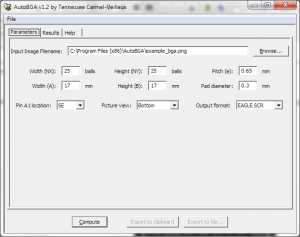
I have just recently finished work on version 1.2 of an open-source tool called AutoBGA.
AutoBGA is a program that takes images of ball grid arrays (BGAs) from datasheets to automatically construct a PCB footprint of the package. The generation of such footprints is usually a tedious and error-prone process because of the large number of pads which must be precisely placed and named.
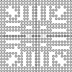
For many BGA footprints with a mostly full grid, the traditional method is to use some automated scripts to obtain a large grid with every ball drawn, from which missing balls are manually deleted. However, for complex patterns of many modern chips, it becomes a nightmare to do manually. The following footprint for the Texas Instruments AM3517 Sitara ARM processor is an example of a large BGA with a hard to reproduce pattern:
My friend Olivier Allaire had this exact chip for which he had to generate the footprint, along with several other BGAs in use in his SPCube interface card for the SONIA project. It took him quite a while to do it by hand, so it gave me the the idea to automate the process using image processing.
After a few evenings of hacking, I had developed version 1.0 of AutoBGA. It is written in Python and uses the Python Imaging Library as well as wxPython for the GUI.
To extract the BGA pattern from an image, there are many possible ways to go. The straightforward naive algorithm involves scaling the image down to the size of the BGA and thresholding it. Since a lot of datasheets contain measurement lines and annotations overlaid on top of the ball pattern (see the picture above), this algorithm is easily fooled.
My algorithm is based on several heuristics and it works as follows:
- Threshold the image assuming mostly black over white.
- Separate the image into NX by NY bins of pixels, where NX and NY are the numbers of balls horizontally and vertically.
- For each bin, apply cleaning:
- Any horizontal line containing more than 70% of pixels is cleared
- Any vertical line containing more than 70% of pixels is cleared
- Any bin whose approximate convex hull is less than 20% of the width or height is cleared
- At this point, most measurement lines and artifacts have disappeared
- Use either Gonzalez & Wood’s iterative thresholding algorithm, or Otsu’s method tresholding to determine which bins are “full” (contain a ball) or “empty”. The threshold is calculated as if we had an NX by NY pixels image, with the number of black pixels lit in each bin being the “intensity value”.
- Generate a named grid according to BGA ball nomenclature rules
- Cast the names onto the balls detected
The choice of algorithm in step 4 is based on some more heuristics developed through testing.
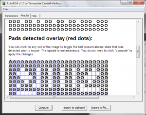
After much testing, this algorithm has proven very robust. While the current version of AutoBGA (1.2) has a feature to edit the detected ball grid to correct mistakes, this has not proven to be necessary in all my tests with very weird/bad images.
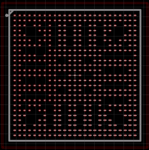
AutoBGA also can draw the footprint outline for the silkscreen, as well as the courtyard, based on IPC7351 rules. The following image shows the result when drawn in EAGLE.
The following formats are supported for CAD output:
- EAGLE script (full-featured)
- XML (full-featured and generic enough to be used as a source for any other CAD program through a converter)
- TSV (just the positions and names of the balls)
I have released the source code of AutoBGA on a Google Code page under a BSD license. If anyone wants to add support for more CAD output formats, you’re more than welcome to do so. Right now, the tool is production-ready and works under both Windows and Linux. I assume it works under MacOS, but it is untested. As long as the library dependencies are met, it should work.


