Project files are at the end of this article
Disclaimer
The intellectual property for this project does not belong to ETS since it was designed while I was doing an internship away from ETS, using my own CAD software licenses on my own computer. I have given away all rights to this design to the public domain, which includes unlimited usage by SONIA and others. The firmware is an intellectual property of Jean-François Dionne and ETS, and as such, is not available on this page (although it is very simple to rewrite it). Neither Tennessee Carmel-Veilleux, SONIA or ETS are responsible for any material or moral damage, lost income or fitness of purpose related to this design. Liability in following these instructions lies with the executer.
Introduction
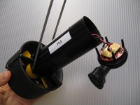
This is a project I have designed while involved in the SONIA student club at Ecole de Technologie Supérieure (ETS). Since 2005, SONIA has been using the great BTD150 ROV thrusters from SeaBotix for their vehicle. During the 2006-2007 competition year, we used a proprietary LIN-protocol drive to replace the BTD150’s default I2C version.
In 2007, we switched our drives to this model, which was designed to match the vehicle’s main peripheral CAN bus so that the LIN support could be dropped. We also wanted a 100% non-proprietary circuit so that every member of the team could look at the plans without signing an NDA. This is why the CAN version was designed.
Pictures
Requirements
The requirements for this drive were simple:
- The mechanical form factor must fit within the BTD150’s housing
- The PCB must be at most 4 layers
- A CAN bus port supporting at least 125k baud must be present
- Input voltages from 15 to 26V must be supported
- Maximum thruster power (75W) should be supported continuously at 24V
- Thruster speed must be variable between 0 and 100% with at least 64 discrete level but not necessarily closed-loop controlled
- Current-limiting and stall-protection circuitry must be provided to enable these functions in the firmware
- Board temperature and current must be monitored
- Parts should be easy to source for at least 3 years at many different distributors
Design (files at the end)
Microcontroller and CAN communication
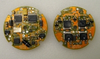
With these requirements in mind, I designed a circuit around the PIC16F690 motor-control microcontroller (MCU). This MCU is easy to program with common tools and is very robust. It also contains an enhanced PWM module that can do hardware-assisted current limiting, as well as configurable signaling different types of H-bridges used in brushed motor control. I used 3 square pads with 0.1″ spacing in an “L” configuration for the ICSP (In-circuit serial programming) port, with the ground on a fourth flying lead. A pogo-pin adapter went between the drive PCB and the PIC programmer.
Although the PIC16F690 has SPI, I2C, USART/LIN ports, it does not possess a CAN controller. For this task, we used an external MCP2515 SPI-bus CAN controller. The CAN transceiver PHY is the low-cost MCP2551. This chipset proved simple to integrate and supported the minimal requirements we had for CAN operation. The 8MHz crystal oscillator XT1 provides a low-jitter, high accuracy clock for the CAN controller. The MCU is clocked from an internal 8 MHz RC oscillator.
H-Bridge and monitoring
The drive uses a classic symetrical MOSFET H-Bridge with low-side current monitoring. It uses an original high-side drive that is well adapted to infrequently changing motor direction and very small to implement on the PCB. High-side gate turn-off is deliberately faster than turn-on, to prevent gate breakdown because of too high a voltage during the transition from conduction to turn-off. A conscious choice was made to omit low-side freewheeling diode because of space constraints. Therefore, the drive uses the internal body diodes of the low-side N-channel MOSFETs for that purpose.
The gate drive logic is meant to have static high-side “direction selection” mode and very fast, low-impedance gate-drive on the low side, to reduce switching losses. The gate-driving PWM signals are generated by the PIC16F690’s enhanced PWM module and feature hardware current-limiting cutoff from an internal comparator tapped on the current measurement. The low-side dual gate driver is the ubiquitous TC4427. The PWM frequency is programmable such that the drive can receive either a “default” configuration or be tuned to the particular load with which it is used.
To monitor the current, a single-ended measure is made on a low value shunt. The OP-amp, a TLV271, was chosen to also act as a first order filter by way of its GBWP (Gain-Bandwidth Product). Since the voltage gain is very high (approx 40 dB), the low bandwidth of the amp restricts response time, which forms a filter around 30kHz, depending on fabrication processes. Extra filtering can be added to obtain an average current rather than a more classic exponential sawtooth by way of an RC filter formed by R4 and optional C4.
The temperature and supply voltage signals are converted by the MCU’s internal ADC. A low-cost MCP9701 temperature transducer is used to get a linear transfer function between degrees Celcius and volts.
Power supplies
The power supplies are provided by inefficient but robust 78Lxx regulators in SOT89 packages. The NJR units selected have been shown over time to exhibit extra robustness when operated at high temperatures for long periods of time. As much decoupling and bulk filtering was added as space would allow. The only compromise was made in the input filter. An MCP120T reset monitor can be patched-on if device lock-up occurs because of large dips on the input supply (ie: sagging caused by large transient loads). Since the built-in Power-On Reset of the MCU is used, this condition can occur when the power supply at the end of the cable is marginal. Experience has shown that this is not necessary except in pathological cases of high-loss source-to-thruster power path.
Layout and assembly
Much care was devoted to the routing of the drive’s PCB to insure reliable operation in harsh conditions. After all, the drive is fully enclosed and a brushed DC motor is spinning very fast with a high load ! A heat spreader can be installed on top of the MOSFETs and held in place with the center retaining screw. It may seem useless, but it more than doubles the available surface for heat dissipation in the ambient environment.
The PCB is a 4-layer FR4 PCB with standard 1/16″ (62.5mil) thickness. Minimum trace width is 10 mils and spacing is 10 mils. Contour routing is important and the provided board outline layer is the external contour, not the tool path. All footprints were drawn for ease of hand soldering (roughly equivalent in most cases to “M”-series IPC-7351 standard land patterns). As mentionned above, a programming tether must be constructed to program the PIC. It is very easy to do with 3 pogo pins on a small piece of 0.1″-spacing prototyping board and an easy-hook ground lead. Full Gerber and Excellon data is provided in the fabrication archive.
The BOM is available on the last page of the PDF file containing schematics and board prints. This BOM can be used both for assembly and for part ordering. Most parts are from Digikey.
Field deployment
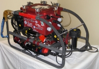
The drive firmware was programmed very quickly by Jean-François Dionne of our team, based on previous work by Jean-Pierre Marcotte. I participated in writing the driver for our main software stack on the embedded PC. This drive was assembled in more than 20 copies. No catastropic malfunction (apart from a single water leak) has ever occured over 3 years of active use as the sole drive on two AUVs and one ASV. Overheating has not occured because the current-limit and stall protection scheme prevents heat build-up.
We have had several occasions of stalled thrusters being driven for hours before someone realized the stall, without a failure. We did in fact burn through a BTD150 winding before the current limiting was in place in the firmware. This drive design has stood the test of time and is the workhorse for SONIA in terms of thruster drives.
Conclusion
I hope this design can be helpful either as is, or as an example of a working design for a fully integrated BTD150 drive. I encourage anyone to use this circuit at large. However, do consult the disclaimer.
If you require the original editable EAGLE-format schematics and board files, I can provide them depending on the application.


Looks great. thank you so much for the design…